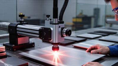
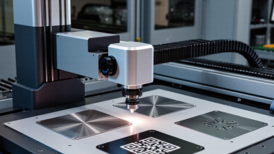
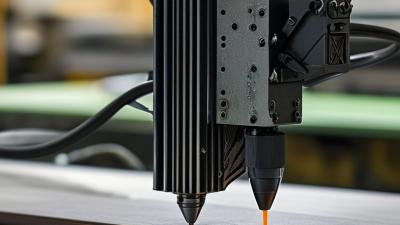
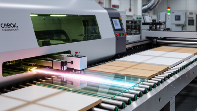
Choosing Fiber Laser Marking Printers in 2026 requires more than comparing prices and wattage. The right machine must match your materials, production speed, marking depth, and quality expectations. Stainless steel, aluminum, brass, coated metals, and engineering plastics can react differently under the same laser settings. A bright showroom sample proves little.
Dr. Valentin Gapontsev, founder of IPG Photonics, described the laser as “a universal tool.” That idea remains useful, but it needs practical judgment. A 20W source may suit serial numbers and shallow contrast marks. A 30W or 50W system may perform better for faster production or deeper engraving. Galvo scanner speed, lens size, pulse control, cooling, software stability, and fume extraction also deserve careful attention. Small details matter.
Look closely.
A reliable buyer should request test samples made from the actual workpieces. Ask for marking speed, line width, contrast, repeatability, and long-term maintenance data. Check whether replacement lenses, field support, and software updates are available in your region. A low purchase price can become expensive when calibration takes too long or spare parts are difficult to obtain.
There is no perfect printer for every factory. That assumption can mislead new buyers. Some suppliers emphasize peak power while overlooking beam quality and operator training. Others promise high speed without showing results on reflective metals. This guide will compare the technical and commercial factors that shape a dependable 2026 purchase. It will also question common marketing claims, because practical performance often looks less impressive than a brochure.
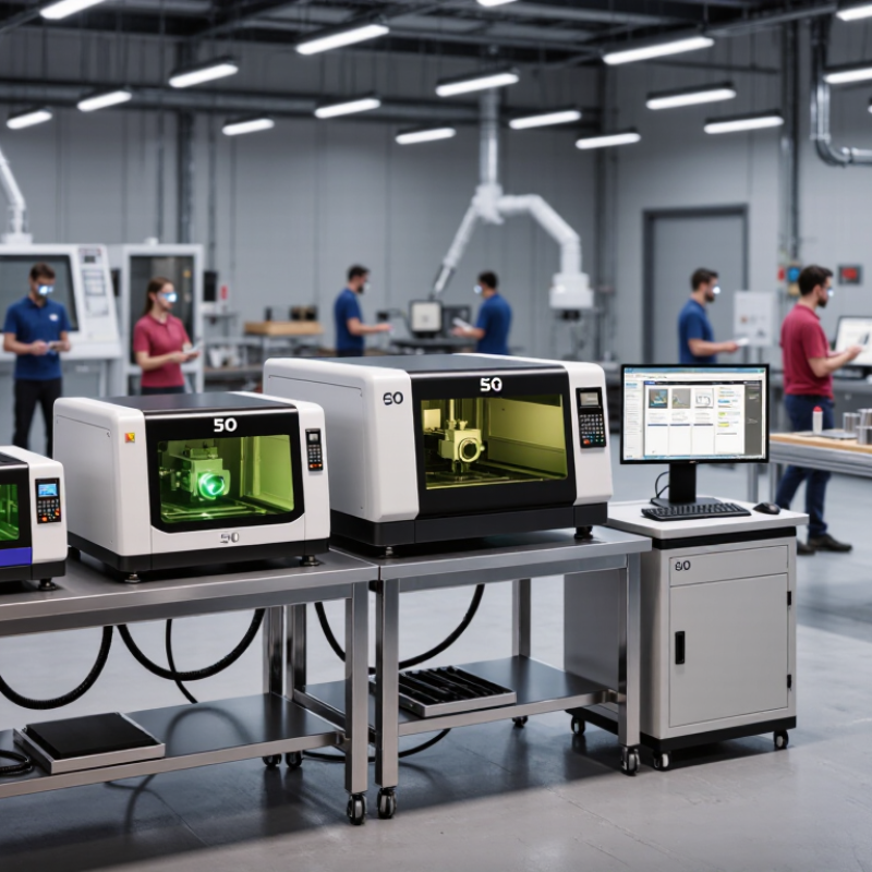
How to Choose Fiber Laser Marking Printers in 2026?
Fiber laser marking printers use a focused 1,060–1,080 nm beam to modify a material’s surface. They can anneal, engrave, or remove coatings without ink, plates, or chemical consumables. The result is usually a sharp, permanent mark on steel, aluminum, copper, and engineered plastics.
The market is expanding steadily. Fortune Business Insights valued the global fiber laser market at about USD 4.25 billion in 2023. Its report projects approximately USD 8.15 billion by 2032. MarketsandMarkets also estimated the laser marking market could grow from USD 3.0 billion in 2023 to USD 4.2 billion in 2028. These figures suggest stronger demand for traceability in automotive parts, electronics, medical devices, and industrial tools.
Application details should guide printer selection. A deep serial number needs different pulse control than a high-contrast logo on anodized aluminum. MOPA sources can offer finer control for plastics and color effects, while higher power supports faster metal engraving. Check marking speed, lens coverage, spot size, cooling, enclosure safety, and software traceability. A wider field may reduce repositioning, but it can sacrifice detail. I would test the actual part before purchasing. Catalog samples often look better than factory-floor results. Dust, curved surfaces, reflective metals, and operator training still matter. Small oversights become expensive.
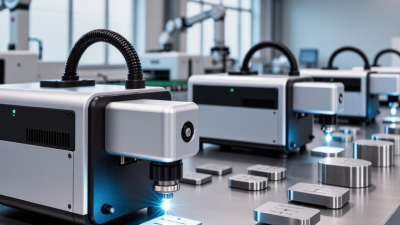
Understanding wavelength helps match a laser marking system with the material and application. Fiber lasers commonly operate at 1064 nm and are widely used for permanent marking on metals, engineering plastics, and electronic components.
Fiber laser marking printers use near-infrared light at approximately 1064 nm. This wavelength is well suited to metal annealing, engraving, ablation, and high-contrast marking. UV and green lasers operate at shorter wavelengths for heat-sensitive materials, while CO₂ systems use a much longer wavelength for many non-metallic materials. In addition to wavelength, compare pulse characteristics, marking speed, power, spot size, software compatibility, safety features, and serviceability before choosing a printer.
Choosing a fiber laser marking printer in 2026 starts with the material, not the machine’s advertised power. Stainless steel, aluminum, brass, coated metals, and engineering plastics react differently to heat. I test a small sample before approving any purchase. A clean black mark on stainless steel may become a pale mark on aluminum. Plastics can also melt, warp, or release unwanted fumes.
Define the marking requirement precisely. Permanent identification, high-contrast logos, serial numbers, and data codes may need different settings. Check the required mark depth, width, contrast, and reading distance. For tiny codes, beam quality and galvo accuracy matter more than maximum wattage. Deep engraving needs repeated passes, which can reduce output. Speed matters, but consistency matters more.
Production conditions often decide the practical choice. Measure daily part volume, surface variation, available floor space, and operator skill. A printer used beside a dusty machining line may need stronger protection and easier lens cleaning. Consider rotary fixtures for cylindrical parts and vision alignment for irregular components. Integrate extraction and guarding where the process requires them. A first trial is rarely perfect. I have seen attractive sample marks fail during long production runs because heat built up between parts. Run a realistic batch, inspect every code, and record settings before committing.
Practical selection reference based on material behavior, marking objectives, throughput, and production environment.
| Material and Application Selection Matrix | |||||||
|---|---|---|---|---|---|---|---|
| Material / Surface | Recommended Fiber Laser Configuration | Typical Marking Objective | Typical Power Range | Typical Speed Range* | Expected Result | Important Process Conditions | Selection Priority |
| Stainless Steel | 1064 nm pulsed fiber laser; 20–50 W for general marking | Permanent identification, serial numbers, QR codes, logos, and dark annealed marks | 20–50 W | 500–3,000 mm/s | High-contrast black anneal or light surface engraving | Use controlled heat input for annealing; multiple passes may be required for depth. | Contrast, corrosion resistance, code readability |
| Aluminum and Anodized Aluminum | 1064 nm pulsed fiber; short-pulse or MOPA configuration for fine contrast | High-speed text, barcodes, QR codes, and decorative contrast marking | 20–30 W | 800–5,000 mm/s | Light or dark contrast; anodized coating can be selectively removed | Avoid excessive heat that can distort thin parts or create uneven shading. | Speed, contrast uniformity, low heat input |
| Carbon Steel and Tool Steel | 1064 nm pulsed fiber; 30–60 W when deeper engraving is required | Deep serial numbers, tooling identification, asset codes, and wear-resistant marks | 30–60 W | 200–1,500 mm/s | Durable surface engraving or dark oxide contrast | Use multiple passes for depth; extraction is recommended when smoke or residue is generated. | Depth, durability, cycle time |
| Brass and Copper | 1064 nm pulsed fiber with adjustable pulse width; higher power may improve throughput | Surface marking, electrical-part identification, and shallow engraving | 30–60 W | 300–2,000 mm/s | Variable contrast with limited heat-affected area when optimized | Reflective surfaces require careful focus, power, and scanning-speed control. | Stable processing, reflection tolerance, repeatability |
| Titanium | 1064 nm pulsed fiber; MOPA is useful for color and oxide-control experiments | Medical-device identification, traceability codes, and oxide-color marking | 20–50 W | 300–2,000 mm/s | Dark annealed marks, engraving, or controlled oxide colors | Parameter stability is essential; validate biocompatibility and cleaning requirements separately. | Repeatability, cleanliness, heat control |
| Engineering Plastics | MOPA fiber laser preferred; verify polymer and additive compatibility before purchase | High-contrast text, data matrices, and component traceability | 20–30 W | 500–3,000 mm/s | Color change, foaming, or controlled surface removal depending on formulation | Results vary significantly by polymer, pigment, glass fiber, and flame-retardant content. | Material validation, contrast, low melting risk |
| Painted, Powder-Coated, or Plated Surfaces | 1064 nm pulsed fiber; power selected according to coating thickness | Coating removal for part numbers, inspection marks, and traceability | 20–50 W | 300–2,500 mm/s | Exposed base-metal contrast with defined edges | Confirm coating adhesion and avoid damaging the substrate or creating excessive fumes. | Edge quality, coating selectivity, extraction |
| Production and Machine Specification Checklist | |||||
|---|---|---|---|---|---|
| Production Factor | Low-Volume / Flexible Production | Medium-Volume Production | High-Volume Production | Recommended Evaluation Method | Critical Acceptance Indicator |
| Daily Marking Volume | Up to approximately 500 parts/day | Approximately 500–5,000 parts/day | More than 5,000 parts/day or continuous shifts | Calculate total cycle time, including loading, focusing, marking, and unloading. | Required output is achieved without reducing mark quality. |
| Marking Field | 100 × 100 mm or 110 × 110 mm is often sufficient | 110 × 110 mm to 175 × 175 mm for larger parts | Select the smallest field that covers the part to preserve optical resolution | Measure the largest marking area and the smallest required character or code element. | Complete coverage with readable fine details. |
| Automation Level | Manual fixture and foot-pedal or software trigger | Pneumatic fixture, rotary axis, or barcode-driven job selection | Conveyor, robot, vision system, PLC, and automatic code verification | Confirm I/O, communication protocol, trigger response, and data interface compatibility. | Reliable integration and prevention of wrong-part or wrong-code marking. |
| Marking Requirement | Surface contrast and basic permanent identification | Readable 1D/2D codes, repeatability, and moderate durability | High-speed traceability, verification, and defined depth or contrast limits | Test the smallest character, quiet zone, code grade, and durability after cleaning or abrasion. | Verified readability throughout the expected product life. |
| Work Environment | Clean indoor workshop with stable temperature and low dust | Production area requiring enclosure, fume extraction, and fixture protection | Interlocked Class 1 enclosure, extraction, guarding, and documented safety procedures | Review laser safety, ventilation, electrical supply, noise, and maintenance access before installation. | Safe operation and stable performance under actual factory conditions. |
| Final Selection Rule | Select the laser source, power, scan field, optics, fixture, and automation package only after testing representative production parts. A successful evaluation should confirm mark contrast, code readability, depth or coating removal, heat-affected area, cycle time, repeatability, and operator safety. | ||||
*Speed ranges are typical starting-point ranges for pulsed fiber-laser applications, not guaranteed production values. Actual results depend on pulse width, frequency, spot size, lens field, hatch spacing, material grade, surface finish, and required mark quality.
Power is not the only buying decision. A 20–30 W fiber laser suits many surface markings on stainless steel, aluminum, and coated parts. Higher power, often 50–100 W, can shorten cycle times or support deeper engraving. However, excessive power may create burrs, heat tint, or distorted edges. Wavelength matters too. Most fiber systems operate near 1,064–1,080 nm, where common metals absorb energy efficiently. Different coatings and plastics may respond poorly.
Speed needs careful testing. A scanner rated at 7,000 mm/s may not maintain clean lines at that speed. Galvanometer response, hatch spacing, pulse frequency, and fixture stability all affect production output. A 2024 Grand View Research market report projects strong growth for laser marking equipment through 2030, reflecting wider industrial adoption. That growth does not make published speed claims universally comparable. Measure completed parts per hour, not only scanner speed.
Precision depends on the focused spot, lens, software, and material flatness. A 20–50 micrometer spot can support fine codes and small characters, but vibration can erase that advantage. Use test grids with actual production parts. Check contrast, edge sharpness, thermal damage, and repeatability. Wavelength changes absorption. Small details matter. My practical preference is cautious: select the lowest power that meets cycle and depth requirements. It usually leaves more process tolerance, though this rule can fail with reflective or uneven surfaces.
Software should match the operator’s daily work, not only the sales demonstration. Look for clear templates, batch importing, barcode support, and controlled user permissions. A reliable interface reduces setup errors on the factory floor. Test the software with real drawings and customer files. Compatibility problems often appear late.
Automation can improve repeatability, but it should not create a complicated maintenance burden. Check communication options, fixture positioning, sensor support, and integration with existing production systems. Safety requires guarded marking areas, interlocks, emergency controls, and suitable extraction for process fumes. Operators need practical training, not just a signed checklist. I once trusted a smooth demonstration too quickly. That assumption can fail.
Tips: Ask for a live trial using your materials, artwork, and production speed. Record setup time, marking consistency, noise, and cleaning needs. Choose a system with accessible service points and clear fault messages. Confirm spare-part availability and software support before purchase. Review compatible metals, coatings, lenses, and file formats. Small differences matter. Leave room for improvement.
Choosing a fiber laser marking printer in 2026 starts with the real production task. Define material, marking depth, daily volume, and required contrast. A machine that looks inexpensive may create costly maintenance later. Calculate total ownership costs over three years. Include energy use, lenses, training, spare parts, and rejected work. Request a sample test using your own components. It reveals focus stability and cycle-time limits better than a brochure.
Reliability should be measured, not simply promised. Request service records, expected component life, and clear warranty exclusions. Check whether the supplier stocks critical parts locally. A delayed scanner or control board can stop production for days. During a factory visit, inspect cable routing, cooling, enclosure fit, and software recovery after power loss. Practical testing may expose awkward maintenance access. That detail matters.
Supplier support often determines whether the printer earns its place. Choose a provider offering installation guidance, operator training, remote diagnostics, and documented response times. Ask who answers after purchase, not only who sells the equipment. Confirm software updates, safety documents, and compatible replacement parts. Compare quotations line by line. One may include commissioning; another may charge separately. Leave room for doubt. Production conditions change, and today’s perfect specification may become restrictive next year.